Gas burners for boilers are a bit different from oil or biomass burners. In gas burners, there are no components dedicated to the previous preparation of the fuel before its spraying (components that are essential in diesel burners). This determines a slightly different structure and function in gas burners. In this article we will explore, in detail, the components that make up the gas burners for boilers, in addition to including two exploded views and some safety tips for the installation of spare parts.
What is a gas burner and how does it work?
A gas burner is a device specially designed to mix the fuel (gas) with the comburent (usually air), to carry out the controlled combustion of the gas. It must always meet certain requirements, such as being able to maintain a stable flame, homogeneously mix gas and air within safe flammability patterns, combust an adequate amount of gas at the desired power, and be efficient. in terms of getting the most out of gas as a fuel.
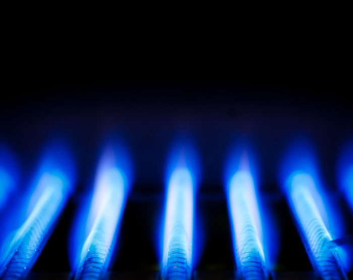
In blue flame burners (such as gas boilers), the air can be supplied in two stages, to achieve more efficient combustion. The primary air mixes with the gas before combustion, while the secondary air mixes with the flame. This generates a very blue and stable flame, as long as there is correct regulation and complete combustion.

Detailed exploded view of a gas burner
As we said before, the burner of a gas boiler and the burner of an oil boiler are similar in structure and function, but they are not identical. Obviously, in the gas burner, the fuel spray components are omitted, in addition to the control and safety components being specific to this type of fuel.
The elements that make up the gas burners for two-stroke boilers are the ones that we will list and explain below. In each case we insert the shortcuts to these products for sale in the Suner store:

- Lid: Plastic or metallic cover that externally protects the burner. It may include a viewer or peephole (an opening in the lid) that makes it easy to observe the internal workings of the burner without the need to disassemble or open it.
- Motor: Electrical component of the burner, whose function is to move both the pump and the turbine. It is designed with a “supportive shaft” that is capable of moving these two gears at the same time.
- Condenser: Electrical component of the burner, whose purpose is to generate and store energy to provide it to the motor at the time of starting, and then to maintain a correct operation.
- Solenoid valve: It is a solenoid-type valve, which means that it incorporates a very uniform magnetic field inside it, which allows the fuel flow to be stabilised just before it passes to the nozzle (jet). It is prepared to detect when there is no pressure, and close, or to detect when there is pressure, and then open.
- Turbine: The turbine is a fan with a centrifugal and cylindrical design, which provides the air necessary for combustion and also favors the extraction of hot air.
- Connectors: These are the so-called multiterminal connectors, designed in female or male format depending on their function.
- Ionization cable: It is the cable that connects and feeds the ionization electrode.
- Ionization electrode: A device that is also called an ionization detector or probe. It is basically a flame detector by means of current. When there is a flame in the burner, this device detects it and creates a closed electrical circuit of which the flame is a part. And when there is no flame, the circuit is interrupted and opens.
- Ignition electrode: This is responsible for causing the spark that ignites the fuel at the end of the burner and generates the flame. It is a fully ceramic insulated metal rod, except for the tip.
- Clapper: Type of retention or non-return valve, which makes it possible for the hot water from the boiler to travel in only one direction (and not both). It prevents the return of the heat carrier to the heating network and also helps to avoid the thermosiphon effect that occurs in the fluids that are heated.
- Deflector or stabilizer: The deflector is located at the tip of the burner barrel. Its design with slots and its position in the burner gives special treatment to the air that passes through it, forming the necessary vacuum to stabilize the flame and create a perfect temperature. (Click here to see spare parts for this part in the Suner store.)
- Flame tube or burner barrel: The flame tube contains the deflector (inside) and the photocell or photoresistor (at the entrance of the flame tube). At its end, the flame exit is also located. Therefore, this component plays a very important role during the fuel vaporization and flame stabilization process.
- Servo Motor or “stepper motor”: High-precision analog or digital component, which specializes in regulating and distributing the airflow inside the burner. It performs this task automatically, in various positions, depending on the number of flames in the burner.
- Fixing flange: It is nothing more than the flange with which the burner is fixed. It gives this support and an exact fixation, as a result of its special connectors.
- Electrode cable: Electrode cable made of silicone.
- Transformer Cable: This is the power cable for the transformer.
- Transformer: Component that is responsible for increasing the input voltage to allow the burner to work. When the boiler starts up, the transformer sends the current to the electrodes so that they cause a spark that ignites the fuel. If the photocell or photoresistor detects that there is a flame, the transformer stops sending voltage to the electrodes and the burner enters the inactive state.
- Programmer or control unit: The control unit is an electronic device specially designed to automatically control the different operating stages of the burner and the boiler, based on the interpretation of the temperature and flame levels. It also handles security and alarm functions.
- The base of the programmer or plinth: It is the support on which the programmer is placed. It has a very important function since, in addition to serving as a base for the control unit, it includes some special connectors that cover all the connection needs according to the functions of the burner.
- Antiparasitic filter: It is a filter against bacteria (such as Legionella) that is installed in equipment that includes water tanks. By reading this IDAE manual you will be able to understand more details about the antiparasitic regulations in heating tanks.
- Pressure switch: The gas used as a boiler fuel is always at risk of explosion. That is why the gas burner requires special safety devices. The pressure switch is one of them (along with the automatic safety valves). A pressure switch, also called a pressure switch, is a device capable of opening or closing the electrical circuit depending on the pressure it detects in the fluid. When pressure is present, the pressure switch allows the electrical contacts to join. When the pressure drops the contacts separate. The safety pressure switch interrupts the operation of the burner whenever it detects that there is a lack of air pressure or excess or lack of gas pressure.
- Flange joint: The flange joint is the joint that allows an exact adjustment of the flame tube fixing flange.
Types of fuels for gas burners
“Gas burner” is a generic term, as various types of gas can be used as fuel for boiler burners. Conventional boiler gases include the following:
- Butane. It is a gaseous hydrocarbon that is obtained from petroleum, and that by nature is colorless and odorless. It produces a totally blue flame. Its strong characteristic odor comes from the addition of an odorant substance (it is almost always mercaptan). This strong odor is necessary for safety reasons. Butane is highly explosive and any leak should be detected as soon as possible. That is also why butane tanks are usually not very large.
- Propane. It is another gaseous hydrocarbon that is obtained as a derivative of petroleum. It is by nature colorless and odorless, with a totally blue flame. It can be explosive when mixed with air, although less so than butane, with respect to which it also has greater energy power per gram. It can be mixed with butane and in some cases, it can replace it.
- Natural gas. Natural gas is a hydrocarbon whose origin is not oil. It is a mixture of combustible gases that accumulate in certain geological layers. Their deposits may appear associated with oil reserves or not. It mainly contains methane, in addition to small percentages of carbon dioxide, helium, or nitrogen. It is considered the least polluting gaseous fuel.
- Other gaseous fuels. There are other gases that can be used as fuel for gas burners. For example, there is hydrogen (obtained from the electrolysis of water), lighting gas (or city gas), and water gas.
Operating stages of a gas burner
A gas burner works through several stages that follow each other automatically, in which one or more components participate at the same time. The operating stages of a gas burner are:
1. Pre-sweep or sweep
The burner fan starts and prevents the combustion chamber to remove any remaining air-gas mixture that may have accumulated during idle time.
2. Power on
The electrical spark on the electrode is activated, and the gas circuit (the pilot burner or the main burner) is opened either at full power, half power, or reduced, as necessary depending on the setpoint temperature. Flame detection is also activated. If there is no flame, the burner is blocked.

3. Running
The burner and the boiler work perfectly until the setpoint temperature is reached. When they reach the setpoint, they turn off automatically. From this point on, the system will perform successive power-ups and power-downs, repeating the entire sequence.
Safety tips for working with gas burners

- The burner is a sensitive, complex, and dangerous part of your gas boiler. It is always sensible that you do not disarm it or fit spare parts to it. It is better to hire qualified personnel with special tools to do it.
- If you notice that any part of your boiler is not working properly (especially if it is the pressure switch, (which is a safety feature), it is better that you stop the operation of the boiler until it is repaired because that way you can avoid major problems or accidents.
- The gases used as fuel for gas burners for boilers are usually odorless. That is why some substance is added to them that gives them a strong smell and that quickly reveals any leak. If you notice any typical gas odor in your burner, immediately close the fuel tap and consult a technician.
- If your burner does not start, or if when you try to start the boiler the display shows an error signal or a red light on, do not force it. Seek help from a technician.
- The burner turbine should make a clicking sound when it starts. If it starts without that sound, that is a sign that it has something wrong and needs to be repaired or replaced: you must do one of those two things immediately. The problem may be in the pressure switch.
- Combustible gases must always produce a fully blue flame. If you notice that the flame is yellowish or has points that are not entirely blue, this is a sign that there is poor combustion in the burner. It is solved with maintenance, spare parts, or taking care of the quality of the fuel.